Project: Flow Meter, Transmitter & Combo Valve Install
Sector: Municipal
Role: Prime Consultant
Description
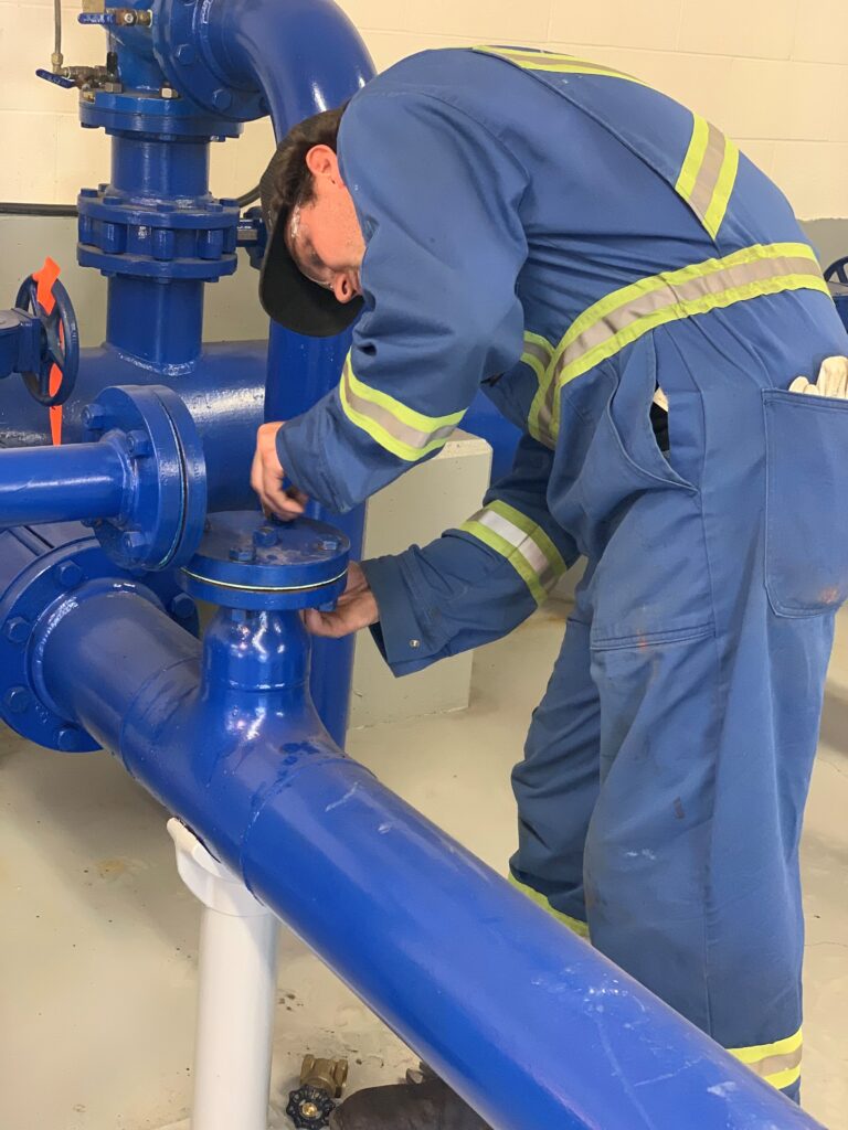
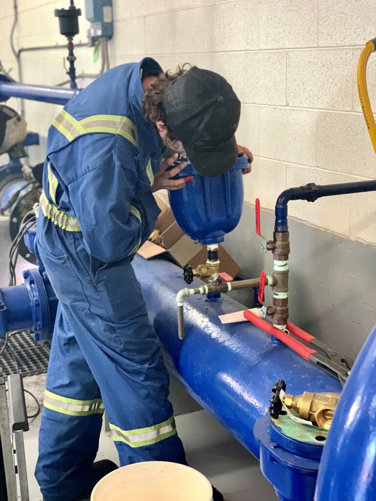
We completed a bypass confirmation test and isolated the P102 valve and locked out the pump. We removed the flange blind, installed a retro fitting flange and installed the piping adapter to install the cam locking hose. Once we tested the bypass system and confirmed all of the connections, we locked out sections of the pipe and isolated all of the required valves so we could remove a section of the 12” piping. We then removed the 12” clamp and drained the 12” pipe.
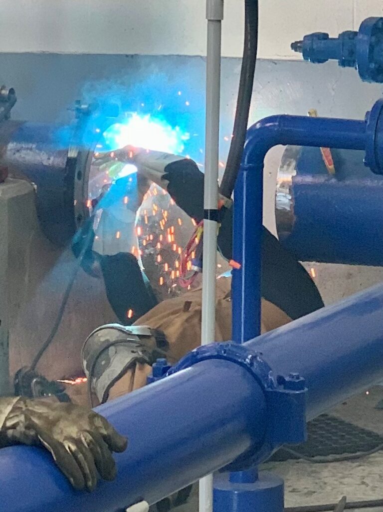
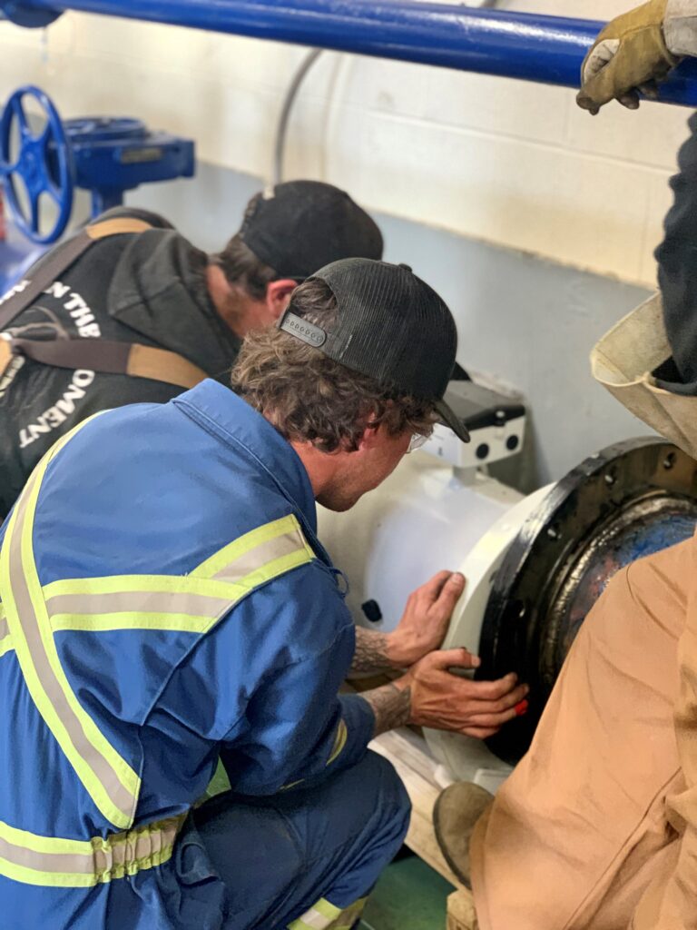
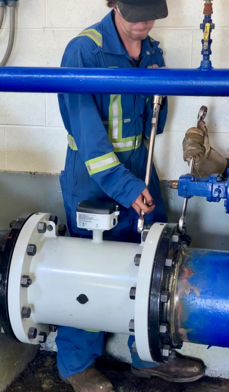
Once the piping was cut to the correct size to fit the flow meter in, we started performing flange leveling & tacked it into place. We welded both flanges to the piping section for the flow meter to bolt up to. We lifted the flow meter into place and installed all of the required gaskets and hardware. We torqued all of the hardware to the bolt spec and opened all isolated valves and removed all locks from the pumps. We also replaced the old ceased auto bleed off with a new valmatic combination air valve.
We then sourced out the existing flow meter circuits and found where it was junction-ed for both the 120Vac power and where the analog output signal went to the control box. After we isolated the circuits and completed the demo of the old flow meter and sensor, we mounted the new flow meter and re-routed the wires into the new meter. After bringing the new flow meter online, we ran through all of the diagnostics and began commission which involved setting all the parameters within the flow meter controller. Then we set up the layout that was chosen for the display and ensured everything was functioning correctly.
We completed a bypass confirmation test and isolated the P102 valve and locked out the pump. We removed the flange blind, installed a retro fitting flange and installed the piping adapter to install the cam locking hose. Once we tested the bypass system and confirmed all of the connections, we locked out sections of the pipe and isolated all of the required valves so we could remove a section of the 12” piping. We then removed the 12” clamp and drained the 12” pipe.
Once the piping was cut to the correct size to fit the flow meter in, we started performing flange leveling & tacked it into place. We welded both flanges to the piping section for the flow meter to bolt up to. We lifted the flow meter into place and installed all of the required gaskets and hardware. We torqued all of the hardware to the bolt spec and opened all isolated valves and removed all locks from the pumps. We also replaced the old ceased auto bleed off with a new valmatic combination air valve.
We then sourced out the existing flow meter circuits and found where it was junction-ed for both the 120Vac power and where the analog output signal went to the control box. After we isolated the circuits and completed the demo of the old flow meter and sensor, we mounted the new flow meter and re-routed the wires into the new meter. After bringing the new flow meter online, we ran through all of the diagnostics and began commission which involved setting all the parameters within the flow meter controller. Then we set up the layout that was chosen for the display and ensured everything was functioning correctly.

We then sourced out the existing flow meter circuits and found where it was junction-ed for both the 120Vac power and where the analog output signal went to the control box. After we isolated the circuits and completed the demo of the old flow meter and sensor, we mounted the new flow meter and re-routed the wires into the new meter. After bringing the new flow meter online, we ran through all of the diagnostics and began commission which involved setting all the parameters within the flow meter controller. Then we set up the layout that was chosen for the display and ensured everything was functioning correctly.