Project: Vertical Turbine
Sector: Municipal
Role: Prime Contractor
Description
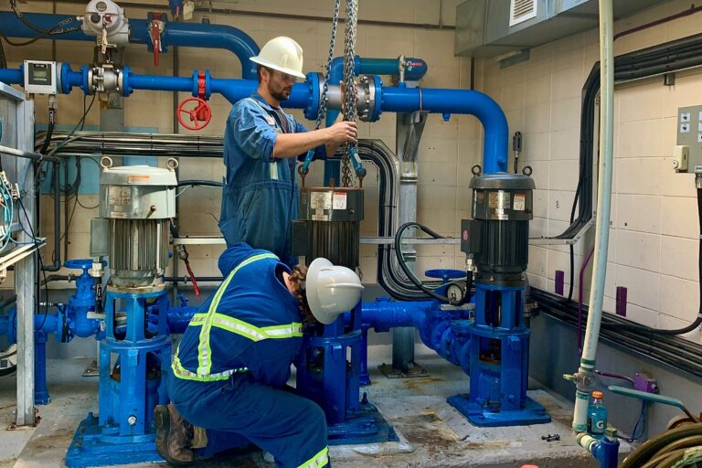
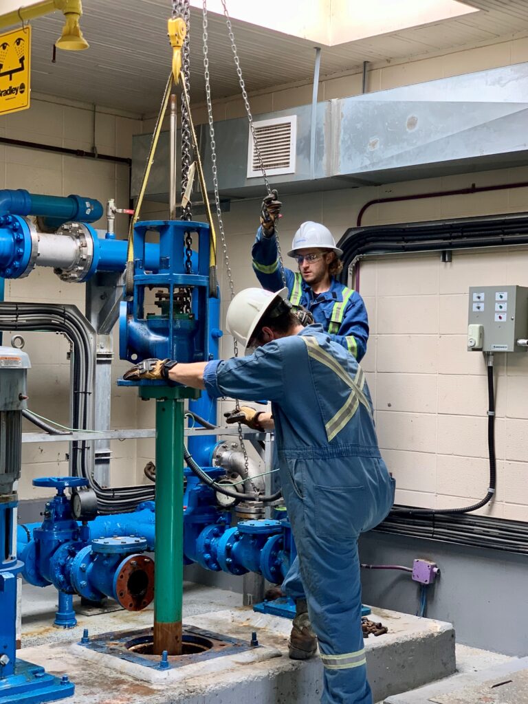
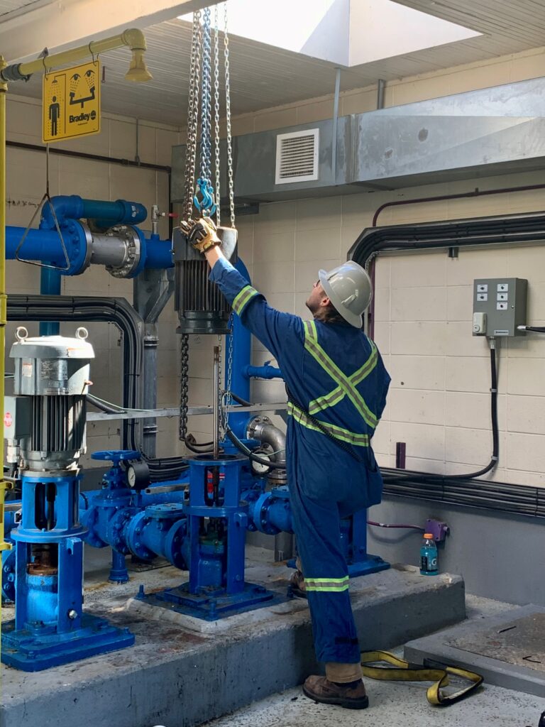
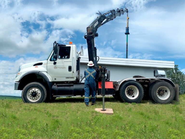
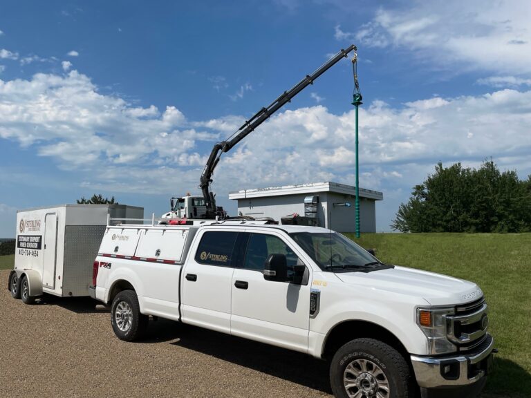
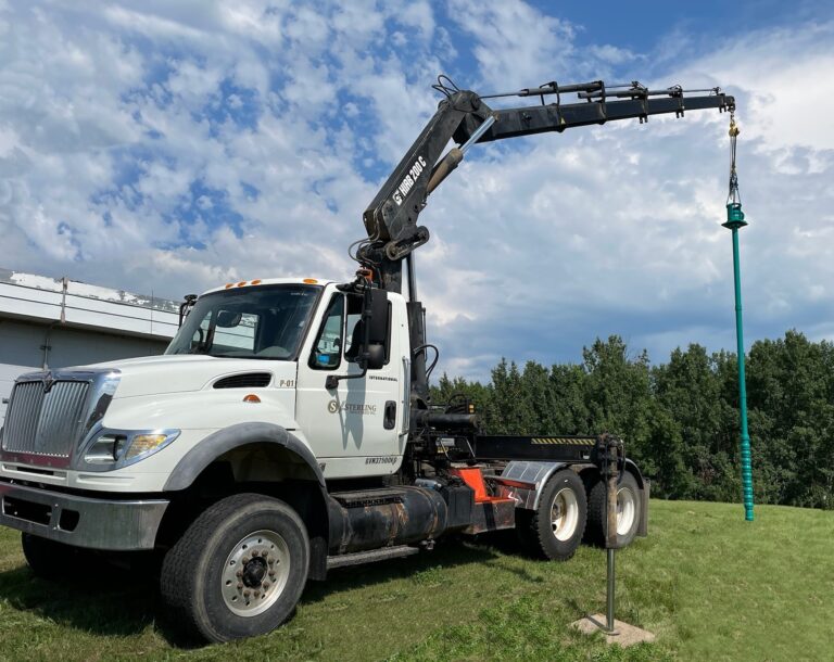
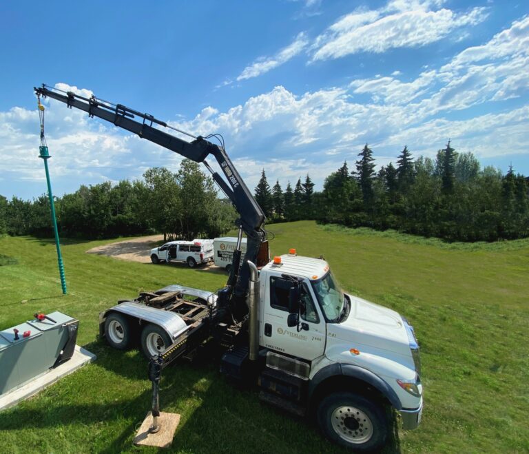
Onsite: After completing all safety checks and walk-thrus with the client we closed off the valve to complete mechanical isolation of the pressurized system. We began to disassemble the motor and removed the roof access in order to get the winch from the picker to drop into the building. Once the motor was unbolted from the pump shaft and casing, we hoisted the motor section out first and loaded it into the enclosed trailer. Piece by piece we removed all components of the vertical turbine and lifted them all out of the well opening with the picker and an
Onsite: After completing all safety checks and walk-thrus with the client we closed off the valve to complete mechanical isolation of the pressurized system. We began to disassemble the motor and removed the roof access in order to get the winch from the picker to drop into the building. Once the motor was unbolted from the pump shaft and casing, we hoisted the motor section out first and loaded it into the enclosed trailer. Piece by piece we removed all components of the vertical turbine and lifted them all out of the well opening with the picker and an assortment of rigging gear. After completely removing the vertical turbine from the well, dismantling and loading/securing it in the trailer, we covered the well opening and returned to the shop where we continued our work on all the pieces from the vertical turbine.
Shop: We ensured all the new and old components are free from any burrs/uneven/damaged faces. We cleaned any powder coating and or paint from bowl mating faces. We then confirmed the bowl shaft was true by using a dial in the middle and both ends of the shaft and ensured it was within .005”. We then set the sand collar on the measurements and tightened both set screws to ensure the sand collar will not
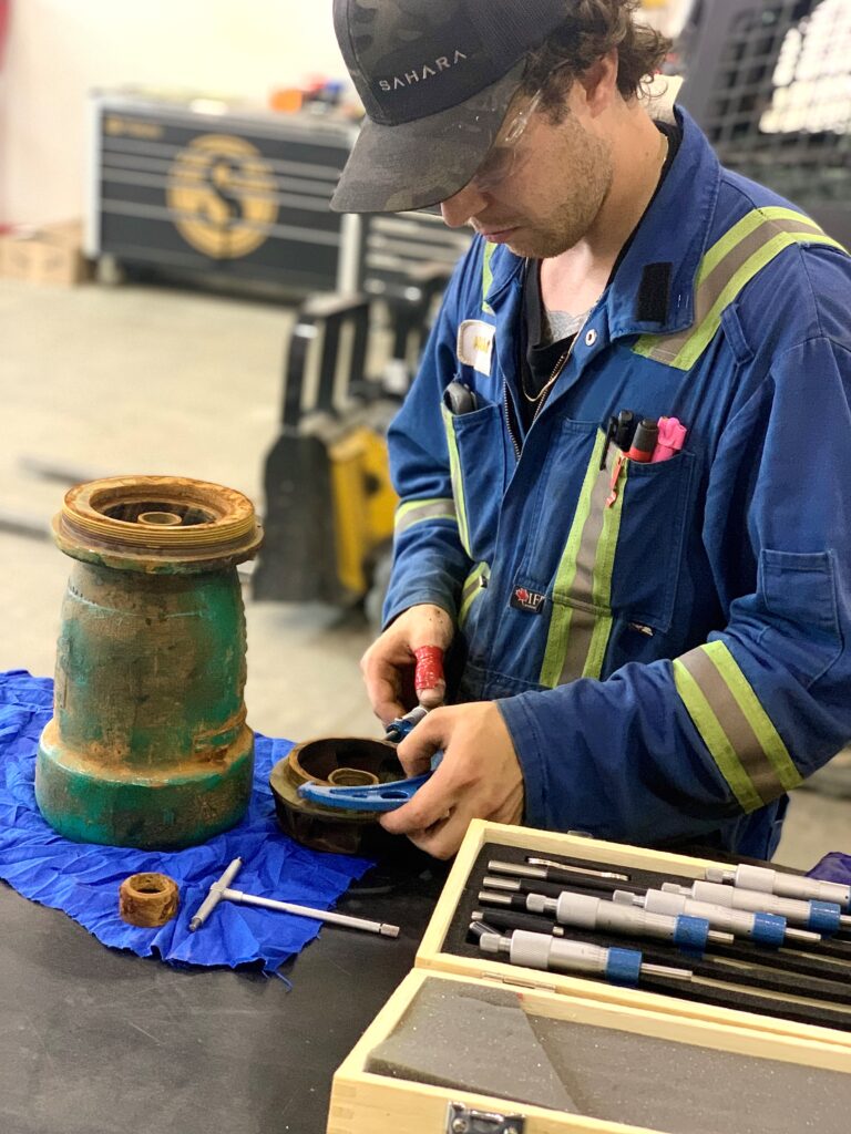
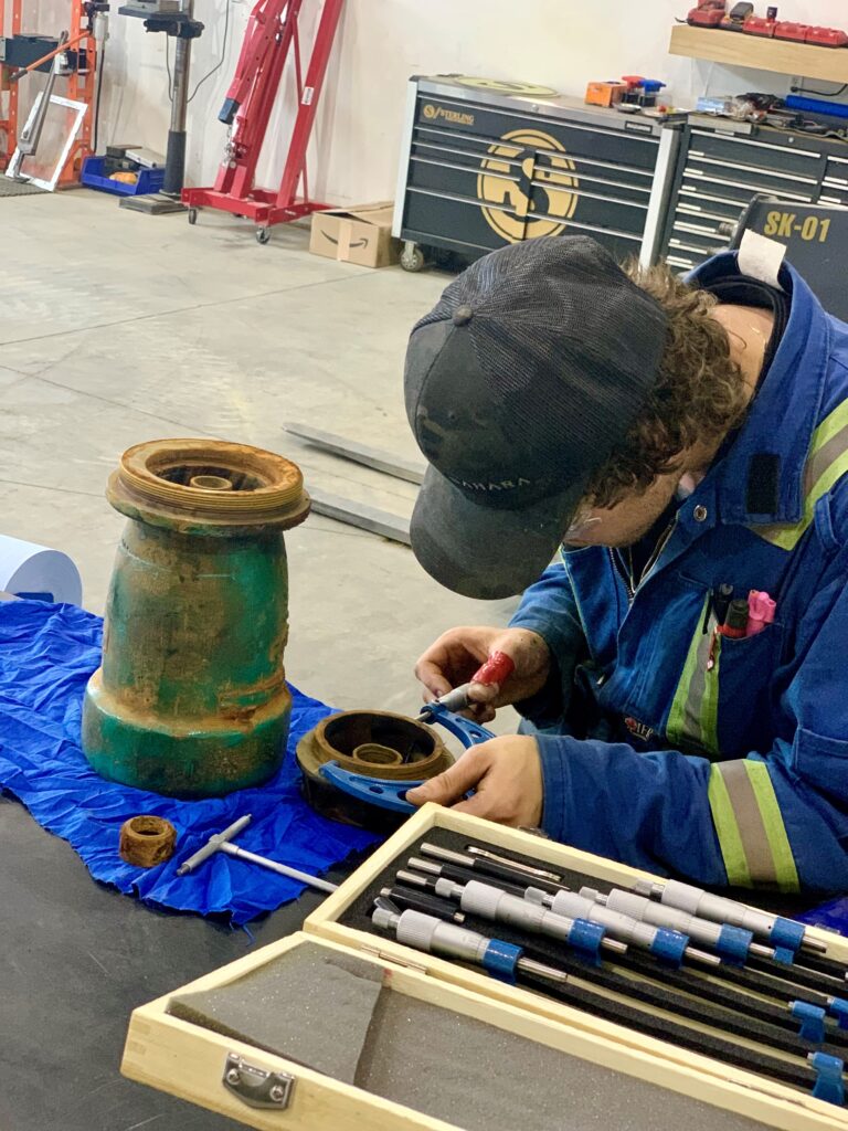
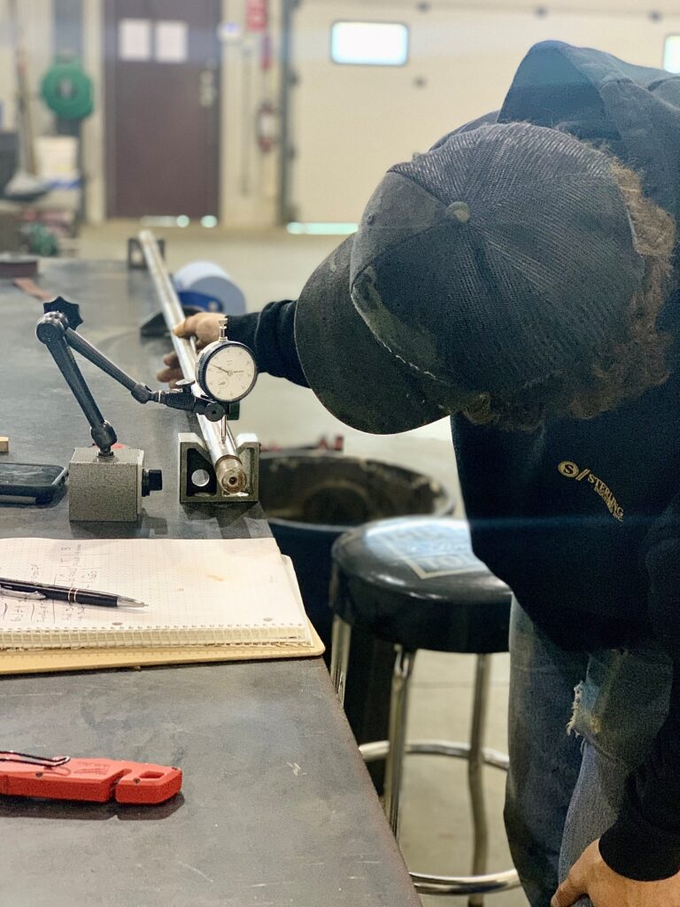
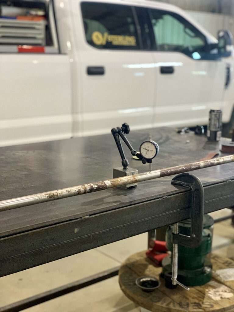
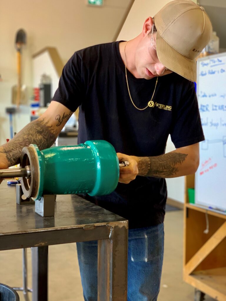
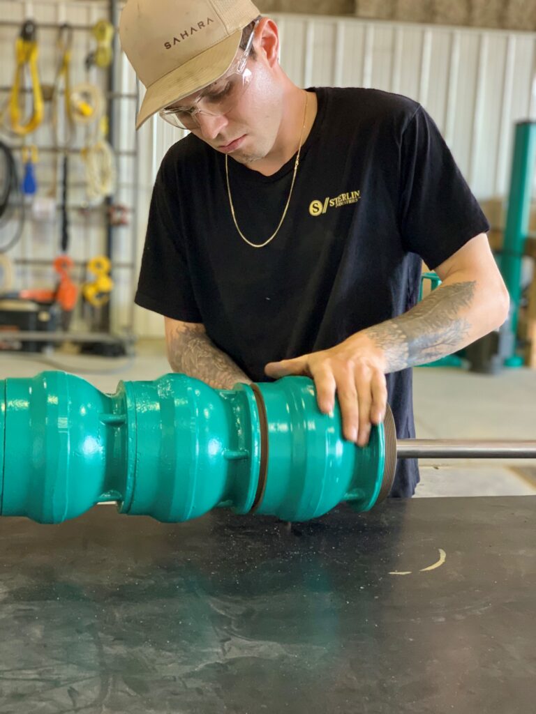
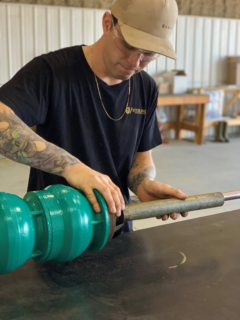
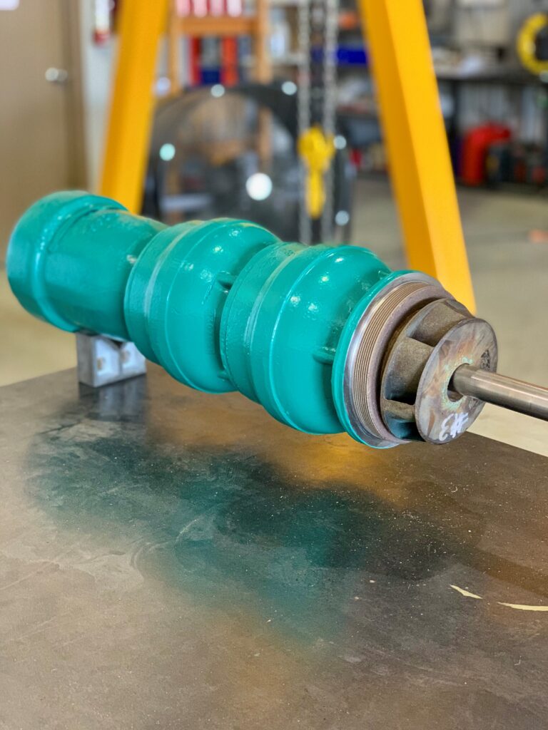
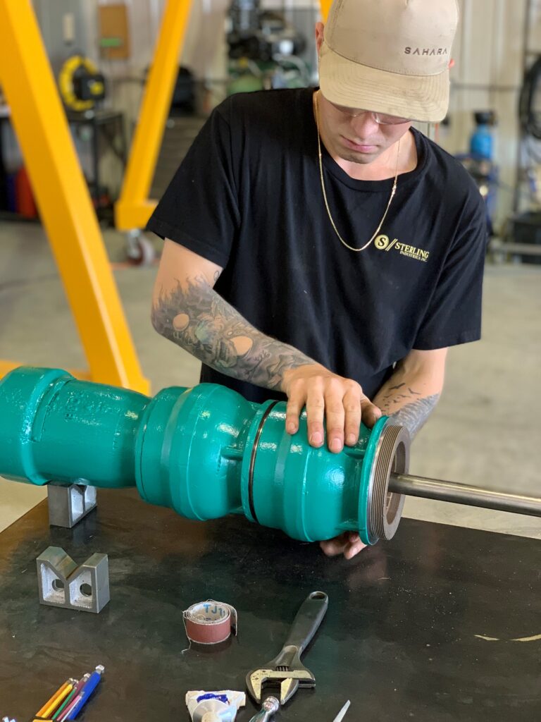
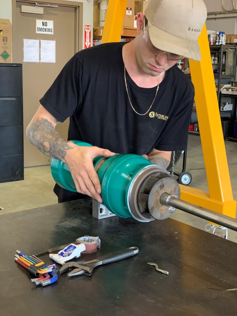
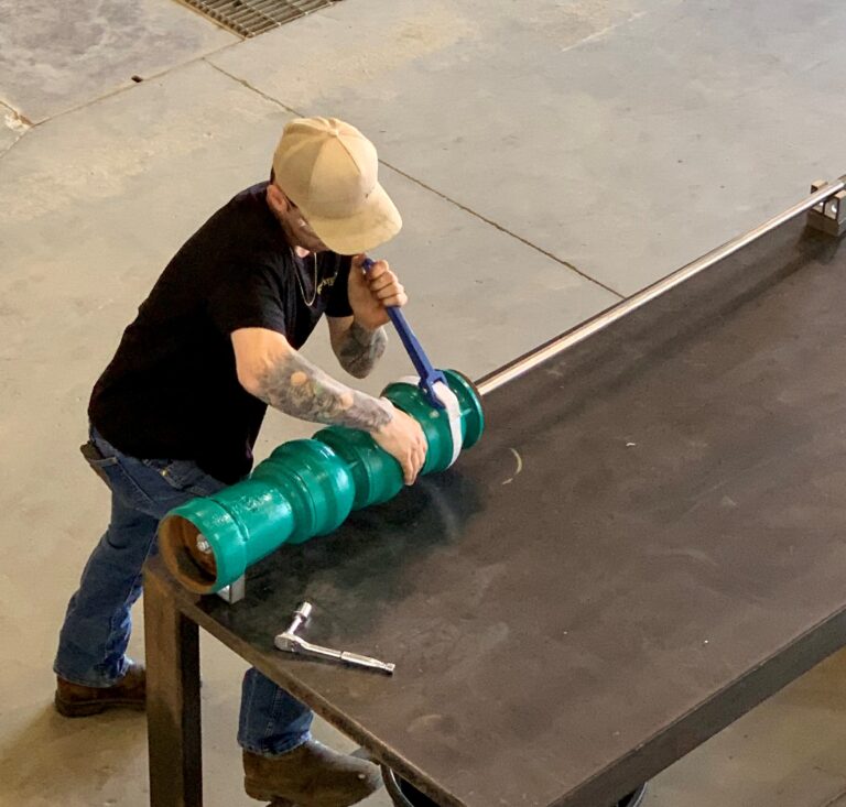
change its placement. We used a bolt & washer to secure the bottom of the bowl shaft to hold it in place for proper impeller installation. We slid the first impeller onto the shaft and confirmed clearance of less than 0.016” from the impeller wear ring & bowl wear ring. We then slid the tapered split brush onto the shaft to set the impellers position. After the first impeller has been set and the two bowls are in place, we then confirmed rotation and float assembly and then tightened the bolt and the washer onto the bottom of the bowl shaft and insured we got proper impeller placements. Once all the bowls and impellers have been set on the bowl shaft and the rotation & float have been confirmed, we then confirmed the shaft stick out of the top of the assembly and measurements matched the original documents. We torqued all the bowl bolts to the required specifications.
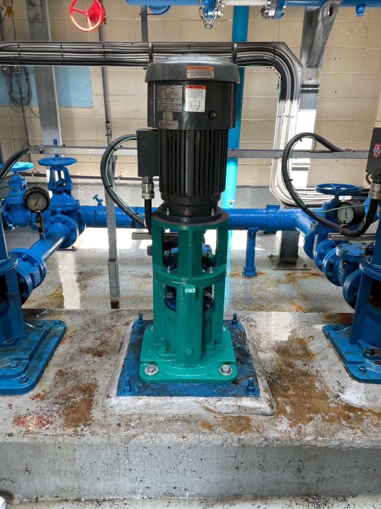
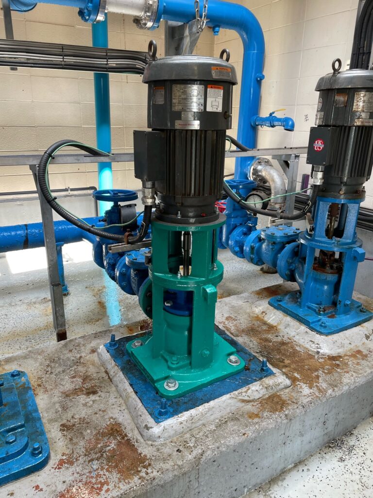
Onsite: Once we arrived on site and completed all safety reports and walk-thrus, we unloaded and assembled all of the VT pump components on site. We then cleaned all of the required parts and used food grade grease on threads & fittings before we lifted the VT pump assembly into the access roof. We then lowered the VT pump assembly into the water reservoir and mounted the discharge head to the mounting block. We then installed all discharge flange hardware & torqued it to spec. We rewired the drive motor and confirmed the rotation. We then set the impeller float on the VT pump assembly and performed a function test on P2 and commissioned the pump. The pump functioned as intended.
assortment of rigging gear. after completely removing the vertical turbine from the well, dismantling and loading/securing it in the trailer, we covered the well opening and returned to the shop where we continued our work on all the pieces from the vertical turbine.
Shop: We ensured all the new and old components are free from any burrs/uneven/damaged faces. We then confirmed the bowl shaft was true by using a dial in the middle and both ends of the shaft and ensured it was within 0.005″. We then set the sand collar on the measurements and tightened both set screws to ensure the sand collar will not change its placement. We used a bolt & washer to secure the bottom of the bowl shaft to hold it in place for proper impeller installation. We slid the first impeller onto the shft and confirmed clearance of less than 0.016″ from the impeller wear ring & bowl wear ring. We then slid he tapered split brush onto the shaft to set the impellers position. After the first impeller has been set and the two bowls are in place, we then confirmed rotation and float assembly and then tightened the bolt and washer on the bottom of the bowl shaft and insured we got proper impeller placements. Once all the bowls and impellers have been set on the bowl shaft and the rotation and float have been confirmed, we then confirmed the shaft stick out of the top if the assembly and measurements matched the original documents. We torqued all the bowls bolts to the required specifications.
Onsite: Once we arrived on site and completed all safety reports and walk-thrus, we unloaded and assembled all of the VT pump components on site. We then cleaned all of the required parts and used food grade grease on threads & fittings before we lifted the VT pump assembly into the access roof. We then lowered the VT pump assembly into the water reservoir and mounted the discharge head to the mounting block. We then installed all discharge flange hardware & torqued it to spec. We rewired the drive motor and confirmed the rotation. We then set the impeller float on the VT pump assembly and performed a function test on P2 and commissioned the pump. The pump functioned as intended.